Time & time again I see component footprints made that are poorly made, non standard, inconsistent and often downright wrong!
Yet there are tools out there that will enable us to make all our component footprints to a consistent standard, following IPC7351 guidelines and best of all the best tool for this is FREE!!
If you get a datasheet for a part that uses an SOT23 from one manufacturer, you can often guarantee that the recommended footprint dimensions from another manufacturer for the same part will be completely different, perhaps a couple of millimeters difference.
Yet the component itself is almost exactly the same size give or take a gnats kneecap!
This causes libraries to be unnecessarily filled with multiple footprints of variations on the same package yet a single footprint would cover them all.
Following the IPC-7351 component footprint standard from the IPC will enable you to have footprints that work, that are all standard and if made correctly - consistent.
But how?
Simples - get yourself over to www.pcblibraries.com, sign up and get the "Libraries Expert Lite".
This free tool can be installed on all Windows PC's and is regularly updated.
Install it, select the SMT or PTH component family that you are looking for.
 |
| Select the component family |
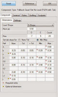
Then simply enter the dimensions from the datasheet.
Hit OK and then your presented with the completed footprint.
Which you can then build a component in your favorite CAD package format from a list of over 20+ major PCB design programs, including CADSTAR, Altium, ORCAD, Pads, Eagle and others.
Import this into your library, make any slight changes so that all the line codes etc used match your library standards and then your able to use it in new parts.
It takes minutes to do, its accurate to the standard, consistent and best of all - the tool is completely free.


2 comments:
A word of warning, If you follow the set-up procedure on their website, ignore the step of "Setup Preferences) as the Lite version only uses the "Default Preferences". Also ignore the bottom line that shows the "User Source" path.
If you want to modify the default\user preferences - you can always modify the preference files in notepad. Just ensure you keep a backup and be aware that you do this at your own risk.
Post a Comment